
CONTACT DETAILS
Telephone: 0086-312-8072668
Fax: 0086-312-8072669
Mailbox: changdidianli@163.com
Website: en.changdidianli.com
Address: Wuluohou Industrial Zone, Weicun Town, Qingyuan District, Baoding City, Hebei Province
1. Material and product structure
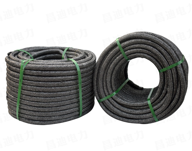
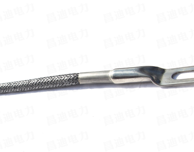
Graphite flexible grounding body is a new type of non-metallic conductive material with stable performance, low resistivity, high and low temperature resistance, acid and alkali corrosion resistance, high current impact resistance, and the material properties will not change. This product is in the form of a cable, and is mainly composed of a stainless alloy stranded body with internal tensile force, a graphite body for dissipating lightning current from the outside, a stainless steel connector connected with the down conductor of the tower and the assembled grounding grid are matched graphite composite connectors constitute.
2. Main performance characteristics
1. Graphite flexible grounding material is a new type of grounding material, and its constituent components have good corrosion resistance. Compared with flat steel and other metal grounding bodies, it has strong corrosion resistance. It can withstand the corrosion of chloride saline soil, sulfate saline soil, soda saline soil and karst soil in coastal areas.
2. The graphite flexible grounding body has a large cross-section and a rough surface to form pores. It has good adhesion to the soil, especially in high-resistance areas.
3. Under the same resistance reduction effect, the graphite flexible grounding body uses less than flat steel and other metal grounding bodies, which reduces the area of soil used and saves land resources.
4. Compared with metal grounding bodies such as flat steel, the graphite flexible grounding body has good engineering performance. It is light and easy to transport and can be excavated in a serpentine shape. It avoids rocks and trees, has a small amount of excavation, does not break and green, and is easy to backfill. , The grounding body is crimped and interconnected, no welding, no power welding machine and other site requirements.
5. Graphite flexible grounding body is a non-magnetic material, and its effective dispersion length is much longer than steel grounding body under power frequency and lightning high-frequency impact. It has good dynamic thermal stability, low temperature rise, and avoids soil sintering and degradation. The blocking effect is outstanding.
6. Environmental protection does not pollute the environment. The use is not restricted by the environmental and climatic conditions, and can be used for a long time in alpine regions and hot and humid regions.
7. Wide application range. It can be widely used in lightning protection and grounding engineering in electric power, communications, railways, highways, petroleum, chemical, construction, military and other departments.
3. Main technical performance indicators
1. Product appearance requirements: the graphite outer surface is smooth and consistent, the drainage layer is tight, and the stainless steel parts are silver gray.
2. Resistivity: ≤3.5×10Ω.m
3. Lightning current impact resistance: 8/20μs, 200kA standard lightning current 18 impacts without damage.
4. Thermal stability: 2kA, 1s) ΔT<673K (400℃)
5. Power frequency impulse current tolerance: 0.5s, 1kA
6. Low temperature resistance: -40℃
7. Tensile strength of grounding body: 17.60kN.
8, Anti-embroidery and annual acid-base corrosion (weight% ratio): no rust ≤0.001%, service life 50 years.
9. The tensile strength of the grounding body connector> 5kN, the connection resistance of the grounding body connector <5mΩ
10. After the connection part of the grounding body is corroded by acid and alkali, the resistance to embroidery and lightning current impact resistance: no rust, no damage to 200kA impact 18 times.
4. Product specifications
The common diameter of flexible grounding module is 300*700mm
The length of the product is mainly designed and produced according to the user's design and the level of soil resistivity requirements.
5. Grounding device form and product consumption
1. According to the characteristics and characteristics of this product and the physical characteristics of the lightning current dissipating in the soil, the shape of the grounding device assembled by this product can be a ring "mouth" shape.
2. In the soil with soil resistivity (≤100Ω.m), the device shape shown in Figure 1 can be used, where the side length of the box is generally ≥8m, the total amount of grounding body is about 32 meters, and the grounding resistance meets the standard requirements.

3. In the soil with soil resistivity (100~500Ω.m), the device shape shown in Figure 2 can be used, where the side length of the box is generally ≥8m, and the four corners of the grounding body extend in the direction of 45°. A radiating line, each ray length is about 8-15m, and the grounding resistance meets the standard requirements.

4. In the soil with soil resistivity (500~1000Ω.m), the device shape shown in Figure 3 can be used. The side length of the box is generally ≥8m, and the four corners of the grounding body extend in the direction of 45° 4 radiating wires, each radiating wire is about 10-20m in length, and the grounding resistance meets the standard requirements.

5. In the soil with soil resistivity (1000~1500Ω.m), the device shape shown in Figure 4 can be used, where the side length of the box is generally ≥10m, and the four corners of the grounding body are along the 45° direction and horizontal 4 radiating lines are extended from the midpoint position, and the length of each ray is about 20-30m, and the grounding resistance meets the standard requirements.

6. In the soil with soil resistivity (1500~2000Ω.m), the device shape shown in Figure 5 can be used, where the side length of the box is generally ≥12m, and the four corners of the grounding body are along the 45° direction and each 8 radiating lines are extended from the midpoint of the frame, and the length of each ray is about 20-30m. The grounding resistance meets the standard requirements.

7. In the soil with soil resistivity (,2000~2500Ω.m), the device shape shown in Figure 6 can be used. The side length of the box is generally ≥15m, and the four corners of the grounding body are along the 45° direction. 8 radiating lines are extended at the midpoint of each frame, and the length of each ray is about 25-30m, and the grounding resistance meets the standard requirements.

8. In the soil with soil resistivity (2500~3000Ω.m), the device shape shown in Figure 7 can be used. The side length of the box is generally ≥15m. The four corners of the grounding body are along the 45° direction and each 8 radiating lines are extended from the midpoint of the frame, and the length of each ray is about 30-40m. The grounding resistance meets the standard requirements. In addition, if the soil at the point where the grounding grid is buried is layered and the resistivity of the underlying soil is obviously low, vertical grounding bodies can be selected at the four corners of the box to further reduce the grounding resistance of the grounding grid.

9. In the soil with a soil resistivity of 3000Ω.m, the double "mouth" shape of the grounding device can be used as shown in Figure 8. The side length of the inner frame is generally ≥10m, and the side length of the outer frame is generally ≥15m. The four frame corners of the body extend in the direction of 45°, and the middle point of each frame extends 8 radiating lines. The total length of each ray is about 40-50m. The grounding resistance meets the standard requirements. In addition, if the grounding grid is buried in layers of soil and the resistivity of the underlying soil is obviously low, vertical grounding bodies can be selected at the four corners of the inner frame to further reduce the grounding resistance of the grounding grid.


6. Installation and construction technology
1. Carry out strictly in accordance with the design requirements of user drawings.
2. Construction of graphite grounding body.
2.1 Construction process
Measure soil resistance → plan grounding grid laying line → excavate the grounding body trench → lead down the connecting wire connecting plate to connect with the pole tower → lead down the connection line and screw the stainless alloy connector of the grounding body → spread the grounding body → assemble the grounding grid →Buried in soil→tamped→measure grounding resistance.
2.2 Laying of graphite grounding body
(1) The section of trench excavation is shown in the figure. The depth can be selected from 0.5-0.8m according to the local soil conditions, and the width is not required;
(2) According to the grounding grid design structure and site topography and soil conditions, it can be excavated in a serpentine shape, avoiding trees and rocks, or through excavation, passing through tree roots and pipes, the shape and design are basically the same;
(3) After the grounding body is laid, choose plain soil for backfilling, which can be compacted in layers, or watering can be used to make the soil backfilled in mud.

2.3 Installation of high-strength graphite down-conductor connectors
(1) Insert one end of the graphite down-conductor into the connecting fitting sleeve, the depth is not less than 170mm;
(2) Use a 600T ring reed press to squeeze the splicing fitting sleeves until they are fully compressed;
(3) Use M16 detachable anti-theft bolts to connect the down-conductor connector to the root of the iron tower.

2.4 Installation of grounding body connector
(1) Place the two graphite grounding bodies to be connected overlappingly in the U-shaped groove;
(2) Use the pressure plate to press the graphite grounding body down in the U-shaped groove until the pressure plate and the two ends of the U-shaped groove completely overlap;
(3) Just insert the anti-return latch.

2.5 According to the material structure of the grounding body and the performance of the lightning current dissipating in the soil, this product generally requires the shape of the assembled grounding grid to be □-shaped or o-shaped. The □-shaped four corners are arc-shaped, and the arc is 30 degrees. The □-shaped and The diameter of the o-shaped ground net shall not be less than 5 meters.
3. Buried depth and measurement method requirements
The burying depth and burying requirements of the flexible graphite grounding body and the grounding resistance measurement method can be carried out in accordance with the technical methods and requirements of the traditional metal grounding body.
7, matters needing attention
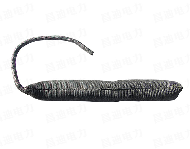
1. The conductive graphite that emits lightning current outside the product is soft and low in strength. It should be protected during transportation and installation to prevent scratches and damage. If damaged, use graphite wire or graphite cloth to wrap it up.
2. When there is a plastic protective film on the outer surface of the grounding body, it should be removed before burying. During the removal process, attention should be paid to the protection of the graphite layer of the grounding body; if the grounding body is equipped with a water-soluble protective film, the grounding resistance should be measured after burying After seven days.
3. The connection head of the stainless alloy connecting wire and the grounding body lock wire must be buried under the soil. It is forbidden to expose the graphite body on the ground.
4. In the salt-alkali ground, salt pond and sea water with heavy chloride ion, the stainless alloy parts in the flexible graphite grounding body structure are all made of 316 stainless steel containing molybdenum.
5. After the product is installed and used, if the grounding resistance value exceeds the standard and fails to meet the design requirements, measures such as extending the radiation line, increasing the size of the grounding body, applying physical resistance reducing agents, and adjusting the soil resistivity until the standard is reached.